Proximity Sensors integration with STONE LCD Module
Stoneitech.com is leading manufacturer with above 15 years of experience of manufacturing LCDs and serving the globe by keeping the products quality high. To meet the high quality standards STONEITECH uses and compliance to the various governing global agencies such as ISO9001, ROHS, CE and F.C.
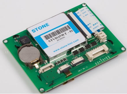
The TFT monitors such as shown in the figure above manufactured by STONE are serving various industries. Few of these industries are:
- Instrumentation Industry
- Public transportation Industry
- Civilian equipment Industry
- Control system Industry
- Electrical Power Industry
- Energy and Automation Industry
The salient features of these LCDs produced by leading STONE are as follows:
- Variety of size range (3.5” to 10.4”)
- Resolution (320x240 to 1024x600)
- Sharp brightness
- RS232 serial universal communication
- USB communication
- Batter backup
Let’s build an application around the STONE LCD. In various industries we need to detect the distances as well as presence of various objects. The presence of objects helps to detect the obstacles in the path or counting of moving objects on the conveyor. Proximity sensors are widely used in the industry to tackle the absence or presence of objects. The presence or absence needs to be displayed on some monitor. We are choosing STONE lcd for displaying.
Introduction to Proximity Sensors:
Proximity sensors detect the presence or absence of objects using electromagnetic fields, light, and sound.
Working Principle:
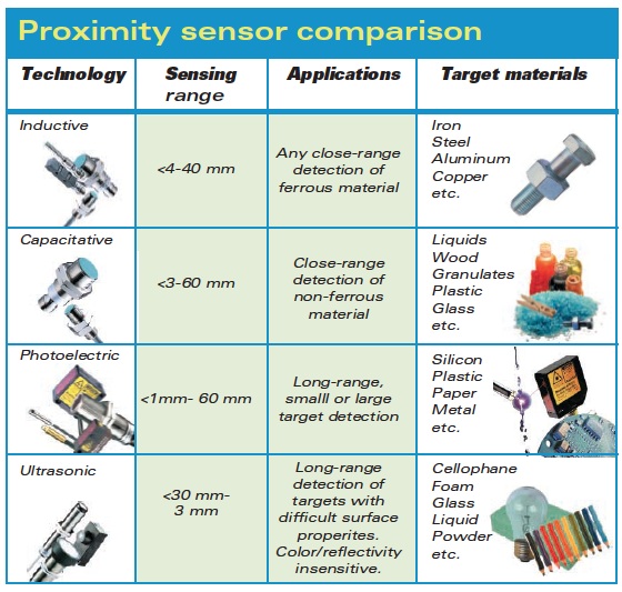
Proximity sensors detect the presence or absence of objects using electromagnetic fields, light, and sound. There are following types, each suited to specific applications and environments.
- Inductive
- Capacitive
- Photoelectric
- Ultrasonic
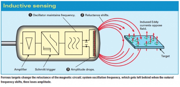
Inductive sensors
These non-contact proximity sensors detect ferrous targets, ideally mild steel thicker than one millimeter. They consist of four major components: a ferrite core with coils, an oscillator, a Schmitt trigger, and an output amplifier. The oscillator creates a symmetrical, oscillating magnetic field that radiates from the ferrite core and coil array at the sensing face. When a ferrous target enters this magnetic field, small independent electrical currents called eddy currents are induced on the metal’s surface. This changes the reluctance (natural frequency) of the magnetic circuit, which in turn reduces the oscillation amplitude. As more metal enters the sensing field the oscillation amplitude shrinks, and eventually collapses. (This is the “Eddy Current Killed Oscillator” or ECKO principle.) The Schmitt trigger responds to these amplitude changes, and adjusts sensor output. When the target finally moves from the sensor’s range, the circuit begins to oscillate again, and the Schmitt trigger returns the sensor to its previous output.
If the sensor has a normally open configuration, its output is an on signal when the target enters the sensing zone. With normally closed, its output is an off signal with the target present. Output is then read by an external control unit (e.g. PLC, motion controller, smart drive) that converts the sensor on and off states into useable information. Inductive sensors are typically rated by frequency, or on/off cycles per second. Their speeds range from 10 to 20 Hz in ac, or 500 Hz to 5 kHz in dc. Because of magnetic field limitations, inductive sensors have a relatively narrow sensing range — from fractions of millimeters to 60 mm on average — though longer-range specialty products are available. Click to view the site
To accommodate close ranges in the tight confines of industrial machinery, geometric and mounting styles available include shielded (flush), unshielded (non-flush), tubular, and rectangular “flat-pack”. Tubular sensors, by far the most popular, are available with diameters from 3 to 40 mm.
But what inductive sensors lack in range, they make up in environment adaptability and metal-sensing versatility. With no moving parts to wear, proper setup guarantees long life. Special designs with IP ratings of 67 and higher are capable of withstanding the buildup of contaminants such as cutting fluids, grease, and non-metallic dust, both in the air and on the sensor itself. It should be noted that metallic contaminants (e.g. filings from cutting applications) sometimes affect the sensor’s performance. Inductive sensor housing is typically nickel-plated brass, stainless steel, or PBT plastic.
Capacitive sensors
Capacitive proximity sensors can detect both metallic and non-metallic targets in powder, granulate, liquid, and solid form. This, along with their ability to sense through nonferrous materials, makes them ideal for sight glass monitoring, tank liquid level detection, and hopper powder level recognition.
In capacitive sensors, the two conduction plates (at different potentials) are housed in the sensing head and positioned to operate like an open capacitor. Air acts as an insulator; at rest there is little capacitance between the two plates. Like inductive sensors, these plates are linked to an oscillator, a Schmitt trigger, and an output amplifier. As a target enters the sensing zone the capacitance of the two plates increases, causing oscillator amplitude change, in turn changing the Schmitt trigger state, and creating an output signal. Note the difference between the inductive and capacitive sensors: inductive sensors oscillate until the target is present and capacitive sensors oscillate when the target is present.

Because capacitive sensing involves charging plates, it is somewhat slower than inductive sensing ... ranging from 10 to 50 Hz, with a sensing scope from 3 to 60 mm. Many housing styles are available; common diameters range from 12 to 60 mm in shielded and unshielded mounting versions. Housing (usually metal or PBT plastic) is rugged to allow mounting very close to the monitored process. If the sensor has normally-open and normally-closed options, it is said to have a complimentary output. Due to their ability to detect most types of materials, capacitive sensors must be kept away from non-target materials to avoid false triggering. For this reason, if the intended target contains a ferrous material, an inductive sensor is a more reliable option.
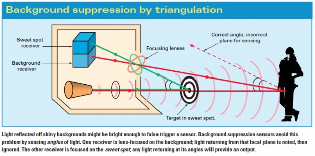
Photoelectric sensors
Photoelectric sensors are so versatile that they solve the bulk of problems put to industrial sensing. Because photoelectric technology has so rapidly advanced, they now commonly detect targets less than 1 mm in diameter, or from 60 m away. Classified by the method in which light is emitted and delivered to the receiver, many photoelectric configurations are available. However, all photoelectric sensors consist of a few of basic components: each has an emitter light source (Light Emitting Diode, laser diode), a photodiode or phototransistor receiver to detect emitted light, and supporting electronics designed to amplify the receiver signal. The emitter, sometimes called the sender, transmits a beam of either visible or infrared light to the detecting receiver.
All photoelectric sensors operate under similar principles. Identifying their output is thus made easy; dark-on and light-on classifications refer to light reception and sensor output activity. If output is produced when no light is received, the sensor is dark-on. Output from light received, and its light-on. Either way, deciding on light-on or dark-on prior to purchasing is required unless the sensor is user adjustable. (In that case, output style can be specified during installation by flipping a switch or wiring the sensor accordingly.)
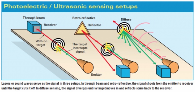
Through-beam
The most reliable photoelectric sensing is with through-beam sensors. Separated from the receiver by a separate housing, the emitter provides a constant beam of light; detection occurs when an object passing between the two breaks the beam. Despite its reliability, through-beam is the least popular photoelectric setup. The purchase, installation, and alignment of the emitter and receiver in two opposing locations, which may be quite a distance apart, are costly and laborious. With newly developed designs, through-beam photoelectric sensors typically offer the longest sensing distance of photoelectric sensors — 25 m and over is now commonplace. New laser diode emitter models can transmit a well-collimated beam 60 m for increased accuracy and detection. At these distances, some through-beam laser sensors are capable of detecting an object the size of a fly; at close range, that becomes 0.01 mm. But while these laser sensors increase precision, response speed is the same as with non-laser sensors — typically around 500 Hz.
Retro-reflective
Retro-reflective sensors have the next longest photoelectric sensing distance, with some units capable of monitoring ranges up to 10 m. Operating similar to through-beam sensors without reaching the same sensing distances, output occurs when a constant beam is broken. But instead of separate housings for emitter and receiver, both are located in the same housing, facing the same direction. The emitter produces a laser, infrared, or visible light beam and projects it towards a specially designed reflector, which then deflects the beam back to the receiver. Detection occurs when the light path is broken or otherwise disturbed.
Diffuse
As in retro-reflective sensors, diffuse sensor emitters and receivers are located in the same housing. But the target acts as the reflector, so that detection is of light reflected off the distant object. The emitter sends out a beam of light (most often a pulsed infrared, visible red, or laser) that diffuses in all directions, filling a detection area. The target then enters the area and deflects part of the beam back to the receiver. Detection occurs and output is turned on or off (depending upon whether the sensor is light-on or dark-on) when sufficient light falls on the receiver.
Ultrasonic sensors
Ultrasonic proximity sensors are used in many automated production processes. They employ sound waves to detect objects, so color and transparency do not affect them (though extreme textures might). This makes them ideal for a variety of applications, including the long-range detection of clear glass and plastic, distance measurement, continuous fluid and granulate level control, and paper, sheet metal, and wood stacking.
How to connect and use a VCNL4010 proximity/light sensor with your Arduino Uno?
The use of proximity/light sensors is important in a variety of applications, including mobile devices and industrial controls.
The VCNL4010 sensor is a fully integrated proximity and ambient light sensor. It is designed for short distance detection — no more than 200 mm — and works best at a distance of about 10 - 150 mm. It is easy to use with any microcontroller that has I2C capability. It is 5V compliant, so you can use it with 3.3V or 5V with no risk of damage.
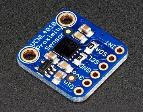
The VCNL4010 proximity sensor. Image courtesy of Adafruit.
Choosing the Right Sensor
In order to decide the right sensor for your application, there are at least three things you should consider:
- First is accuracy. It is important to get a sensor that can measure how close the reading is to the true distance.
- Second, the smallest reading or change in readings that can be reported, or what we call the resolution.
- Lastly, the level of precision or the smallest reading that can be taken repeatedly and reliably.
Now all these three wouldn't be enough if you wouldn't match it properly to the application, you're planning to use it for. If the sensor would be used in an application that would only determine level of liquid, object detection, or distance measurement, perhaps, an Ultrasonic sensor would be a better choice. But if the application involves, light detection or measurement of heat emission, an infrared or proximity sensor should work well.
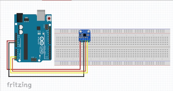
Make the following connections between the sensor and the Arduino Uno:
- Arduino Board 5V to Sensor Vin
- Arduino ground / GND to sensor ground / GND
- A5(SCL) to sensor SCL
- A4(SDA) to sensor SDA
VCNL4010 Power Pins
The VCNL4010 has three power pins:
- Vin
- 3Vo
- GND
Vin is the power pin. The VCNL4010 uses 3 VDC for logic, so a voltage regulator is included on the board to take 3-5 VDC and safely convert it down. Power the board with the same power as the logic level of your microcontroller. 3Vo is the 3.3V output from the voltage regulator. GND is the common ground.
Data Pins Explanation
The VCNL4010 also has three data pins:
- SCL
- SDA
- INT
SCL is the I2C clock pin and it connects to the microcontrollers I2C clock line. SDA is the I2C data pin and it connects to your microcontrollers I2C data line and it and use 3V or 5V logic. INT is the interrupt output used to give you an alert when the sensor detects something.
Installing the Library
To start using the sensor, you will need to download the VCNL4010 library. The library can also be downloaded using the Arduino Library Manager.
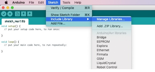
Navigate to "Manage Libraries" in Arduino IDE.
Type "Adafruit VCNL4010" and click Install.
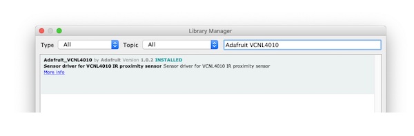
Add the Adafruit VCNL4010 Arduino library.
Trying the Demo
We are ready to test out our setup. Go to File > Examples > Adafruit_VCNL4010 > vcnl4010test and upload this to your Arduino.
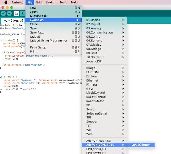
Access the library to run the demo.
Open up the serial monitor at 9600 baud. You should see ambient light and proximity data printed out, showing that you have successfully connected your proximity sensor to your Arduino Uno.
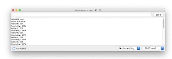
This screen shows up with a successful connection.
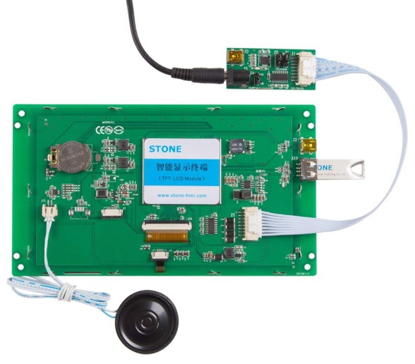
Introduction to STONE TFT-LCD Display Module
The LCD module is STONE STVC050WT-01, which is very convenient to use. we used serial port to display the data, LCD module of STONE receives data and displays it to the module through RS232 serial communication protocol.
Back side of STONE TFT-LCD DISPLAY MODULE
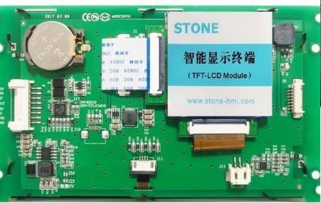
STVC050WT-01-01 is a TFT display and touch controller. It includes processor, control program, driver, flash memory, RS232/RS485/TTL port, touch screen, power supply, etc. It is a powerful display system
Front side of STONE TFT-LCD DISPLAY MODULE
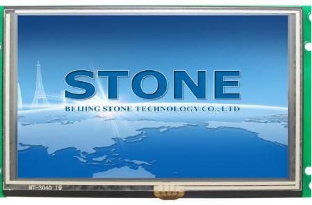
The operating system is simple and can be controlled by any single chip microcomputer. STVC050WT-01-01 can be used to perform all basic functions, such as text display, image display, curve display, touch function, video and audio function, etc. The user interface can be much richer and more diverse. Flash memory can store your data, configuration files, pictures, etc.
- built-in Cortex CPU and driver
- can be controlled by any single chip microcomputer
- show pictures/text/curves
- 65536 color TFT display
- with/without touch screen
- RS232/ RS485/ TTL UART interface and USB port
- wide voltage range
- easy to use.
- Powerful features.
- Cost and time saving.
The Working Principle of STONE TFT-LCD
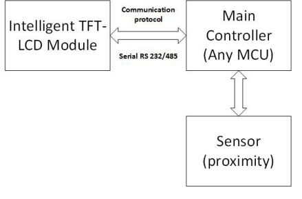
The intelligent TFT-LCD module communicates with the customer's MCU through commands (hexadecimal code), and the MCU then controls the connected device to work according to the commands received.
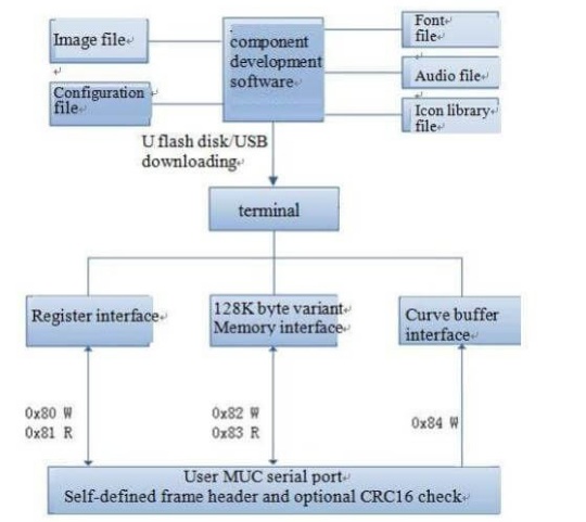
Steps to Develop STONE TFT-LCD
Use STONE's TFT-LCD module in only 3 steps:
- Design a beautiful set of graphical user interfaces.
- Connect directly to the customer's MCU through RS232, RS485 or TTL Plug and play.
- Write a simple program to control the TFT-LCD module by MCU command. (hexadecimal code). TFT LCD module serial command frame consists of 5 data blocks, all serial command or data are expressed in hexadecimal format.
The data transfer In the MSB way. For example, for 0x1234, first send 0x12, then 0x34.
STONE Displays Are Widely Used in Various Industrial Fields
- Medical cosmetology equipment
- Construction machinery and vehicle equipment
- Electronic instruments
- Industrial control system
- The power industry
- Civil electronic equipment
- Automation equipment
- The traffic
About the Use of STONE TOOL Software
At present, the latest version of TOOL software provided by STONE is TOOL2019. Open the software to create a new project, then import the previously designed UI display pictures, and then add your own buttons, text display boxes, etc. STONE's official website has a very complete tutorial on the use of this software. Interested friends can click on the following link:
UI Graphic Design of LCD Module
You can use Photoshop or other image design software to design the pictures file for UI interface. The interface I designed is as follows:
Use TOOL2019 Software to Generate LCD Module Configuration Files
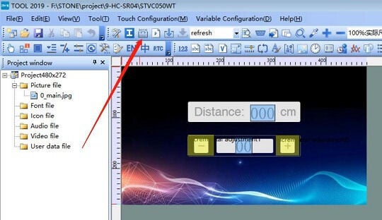
Steps for Loading to the LCD:
- Click the button indicated by the arrow to generate the configuration file
- Download the configuration file into the display module
- Use https://www.stoneitech.com/suppo
rt/downloadto access the download software - Reboot the LCD
- You will have User Interface loaded to the system
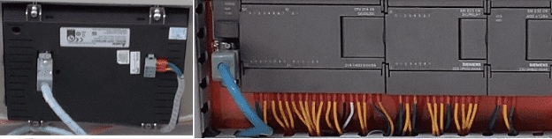
Connecting to the Controller
- Stone LCD have capability of connecting to the controller
- As described in the previous section, use RS-232 serial communication to communicate with the LCD and designed User Interface
- Sample code will be as follows:
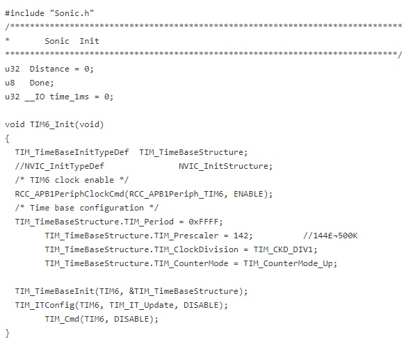
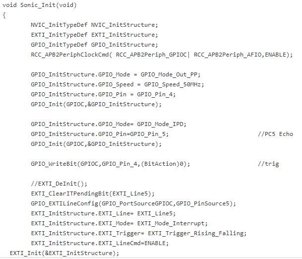
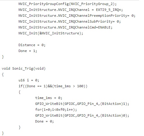
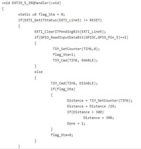
- A such connection is shown in the following picture
More about StoneITech:
Stoneitech.com is leading manufacturer of globe for liquid crystal displays as well as intelligent displays.
They are manufacturing LCDs since 2004. Company is manufacturing quality LCDs which are in compliance with various trademarks and certification agencies such as:
- ISO9001
- ROHS
- CE
- FC
More products can be viewed and purchased by going to the following link:


Comments
Post a Comment